
无油流报警开关Digital No-Flow Timer
The Revolutionary Digital No-Flow Timer for Compressor Lube Systems
DNFT performs monitoring and shutdown functions like No-Flow, Low-Flow or Excessive-Flow for Divider-Block Lubrication Systems. The DNFT is a totally enclosed solid state electronic device for detecting Slow-Flow and No-Flow on in-line progressive lubrication systems. The Digital No-Flow Timer incorporates a crystal oscillator to accurately monitor the cycle time of the lubrication system enabling precision timed shutdown capability. An internal Lithium battery powers it, which is easily replaceable.
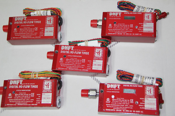
The DNFTs come in three models to switch voltages up to 240 VDC:
LED model
LCC model
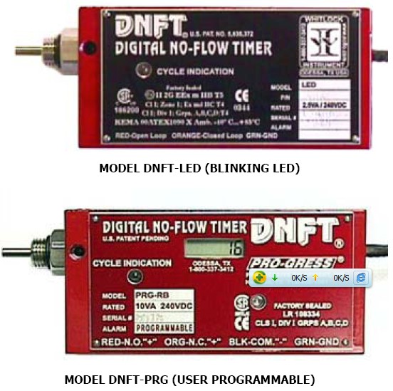
PRG model
产品选型资料下载:
・ DNFT-PRG
・ DNFT-LCC
・ DNFT-LED
・ DNFT-LED-PS
・ DNFT-PRG-PS (Programmable)
・ DNFT-PRG (Standard, Programmable)
DNFT-PRG-PS (Programmable w/ PS Option)
DNFT-LCC 45 Second Alarm
DNFT-LCC 2 Minute Alarm
DNFT-LCC 3 Minute Alarm
DNFT-LCC 4 Minute 15 Second Alarm
DNFT-LED
DNFT-LED-PS
Digital No-Flow Timer (DNFT)
Premier Digital No-Flow Timer (DNFT)无油流开关产品介绍: Monitors Movement of Divider Valve Piston
监测分配器柱塞的运动
Closed Loop or Open Loop Operation
开式或闭式回路 Installs Directly to Divider Valve
直接安装在分配器上面
Not Affected By Temperature or Viscosity
不受温度和粘度的影响
Requires No External Power
不需要外接电源
LED or LCC Cycle Indicator
带LED或LCC循环指示
Dependable “Timed” Shutdown Protection
可靠的停机保护
Explosion Proof Rated for
防爆等级:
Class 1, Division 1, Groups A,B,C,D
CSA Approved
通过CSA防爆认证 CE Approved 和CE防爆认证
SPECIFICATIONS :
Material..................................................Stainless Steel, Aluminum
Temperature Range............................................. -40 F to +185 F
Switch Rating..........................................................2.5VA/240 VDC
Epoxy Encapsulated............................UL LISTED EL-CAST VFR 641
Alarm/Shutdown......................... Factory default for 2 minute alarm
Power.......................................Field Replaceable -Lithium Battery
Battery....................................................................... P/N 000505
Alternate Battery..........................................Radio Shack 960-0418
Divider Block Application...............Dropsa/Lincoln/SBCO/Lubriquip
Warranty...........................................................................2.5 Years
WHITLOCK
DIGITAL NO-FLOW TIMER
506LIT LED-WI-1
DNFT
WHITLOCK INSTRUMENT
07.11.01
1300 N. Texas Odessa, TX 79761
R
915.3373412 Fax 915.335.5926
DIGITAL NO-FLOW TIMER
1.800.337.3412 www.noflo.com INSTRUMENT
U.S. PAT. NO. 5,835,372 WHITLOCK
ODESSA, TX USA
DNFT-LED
P/N: 000506
MODEL Factory Sealed RATED 2.5VA / 240VDC
R
II 2G EEx m IIB T5 CE SERIAL #
C US ClI;Zone1;ExmdIICT4 000506
ClI;Div1;Grps.A,B,C,D;T4 ALARM 2-MIN
186200 0344 P/N
KEMA 00ATEX1090 X Amb. -40° C...+85°C
RED-Open Loop ORANGE-Closed Loop GRN-Ground
DNFT-LED
MONITORS MOVEMENT OF DIVIDER
VALVE PISTON FOR DEPENDABLE
"TIMED" SHUTDOWN PROTECTION
CLOSED LOOP OR OPEN LOOP OPERATION INSTALLS DIRECTLY TO DIVIDER VALVE
NOT AFFECTED BY TEMPERATUREOR OIL VISCOSITY
REQUIRES NO EXTERNAL POWER
LED INDICATOR -CYCLE INDICATION
DEDICATED SWITCH CLOSURE TO MONITOR EACH DIVIDER VALVE CYCLE (PS OPTION)
FIELD REPLACEABLE BATTERY
186200 Cl I; Div 1; Grps. A,B,C,D;T4
KEMA
00ATEX1090
X
Amb.
-40°
C...+85°C
DESCRIPTION
The DNFT-LED is a totally enclosed electronic device, combining the latest technology in microprocessor and transistor components for detecting Slow-Flow and No-Flow of divider block lubrication systems. The DNFT incorporates an oscillating crystal to accurately monitor the cycle time of the lubrication system to enable precision timed shutdown capability. The magnet assembly and control housing mount directly to the divider valve to become an integral part of the lubrication system. The DNFT operates on a field replaceable lithium battery. If battery voltage drops below normal operating levels, the DNFT goes into alarm mode and the unit cannot be restarted. LED models utilize an LED to indicate each cycle of the divider valve. This enables the operator to easily set and monitor lubrication rates.
OPERATION
Lubricant flow through the divider valve assembly forces the pistons to cycle back and forth causing a lateral movement of a magnet linked to the piston. Movement is monitored by the microprocessor which resets the timer, lights the LED, and allows the unit to continue operation, this indicates one complete cycle of the lubrication system. The microprocessor must receive this cycle in a predetermined time or a shutdown will occur. The DNFT will automatically reset alarm circuit when normal operation of divider valve resumes.
WHITLOCK
506LIT LED-WI-2
DNFT WHITLOCK INSTRUMENT
DIGITAL NO-FLOW TIMER
INSTRUMENT
P/N 000506 DNFT-TO-LED DIGITAL NO-FLOW TIMER INSTALLS ON DROPSA/LINCOLN/SBCO/LUBRIQUIP DIVIDER
BLOCK. SWITCH RATING 2.5VA 240VDC
1.
Loosen all Allen head set screws (A) on DNFT (B) and remove magnet housing (C). Do not remove magnet, spring or spacer from magnet housing.
2.
Remove piston enclosure plug (D) from end of divider valve where DNFT will be installed. The DNFT does not have to be installed on the top divider valve. It may be installed on any convenient divider valve, top to bottom. (Notice:Do not install DNFT on Lincoln divider valves with cycle indicator pins or any Dropsa divider valve less than SMX 16.)
3.
Be sure O-ring or metal gasket (F) is in place on magnet housing (C). Screw magnet housing (C) into end of divider valve (E). Torque to 15 foot pounds max.
4.
Slide DNFT (B) all the way onto hex of magnet housing (C). Tighten set screws on hex of magnet housing. Torque 25 inch pounds max.
5.
The LED on the DNFT indicates each divider valve cycle. This enables operator to adjust the lubricator pump for correct cycle time and oil consumption recommended by compressor manufacturer. If LED does not blink with compressor running or by manually pumping oil into divider valve, the DNFT must be adjusted. Normal cycle indication is a bright strobe type blink.
6.
Before adjusting DNFT, divider valve must be cycling. This can be achieved with the compressor running or by manually pumping oil through the divider valve assembly with a hand priming pump.
7.
Adjustment is made by sliding the DNFT (B) all the way on the hex of the magnet housing (C). Tighten set screws on hex of the magnet housing to 25 inch pounds max. Check for LED blink to confirm correct adjustment. If LED does not blink with divider valve cycling, adjust the DNFT back in 1/16" increments. Correct adjustment of the DNFT is confirmed by blinking LED.
8.
All conduit and connections should be appropriate for area classification. Notice: Conduit and fittings must be supported to avoid bending magnet housing.
9. After installing magnet assembly and pre-compressor start-up, it is absolutely necessary to purge all air from dividerblock lubrication system. This can easily be accomplished with a lubrication system purge gun.
10.DNFT must be installed with correct magnet assembly for each divider valve manufacturer.
Lincoln-7/16"-20 extended nose with O- ring Dropsa
Trabon-1994 or earlier 7/16"-20 with metal crush gasket SBCO &Trabon-1995 and later 7/16"-20 with O-ring
Notice: When installing more than one DNFT, each DNFT must be wired to a separate alarm circuit of the control panel, annunciator or PLC to simplify troubleshooting the lubrication system and DNFT.
O-RING OR ALLEN HEAD
INTERNALVIEWOF DIVIDERVALVE METAL GASKET (F) DNFT (B) MAGNET HOUSING SPACER SET SCREWS(2) (A) SPRING #22AWG18"LEADS(7)(I)
(E) (C)
WHITLOCK
RED
DIGITALNO-FLOWTIMER
RED GREEN
INSTRUMENT
GREEN
ORANGE
ORANGE
CYCLEINDICATIONODESSA,TXUSA
MODEL LED
ORANGE
RATED 2.5VA / 240VDC
ORANGE
24S
Factory Sealed
R
C US
LED
CE
II2GEExmIIBT5
SERIAL#
000506
ClI;Zone1;ExmdIICT4
0344
P/N
186200
ClI;Div1;Grps.A,B,C,D;T4
2-MIN
ALARM
MAGNET FIELD REPLACEABLE
KEMA00ATEX1090XAmb.-40°C...+85°C
RED-OpenLoopORANGE-ClosedLoopGRN-Ground
BATTERY
(H)
P/N:000505
DNFT-LED
O-RING
24S
PISTONENCLOSUREPLUG (F)
(D) 1/2“PIPEPLUG CONTROL HOUSING POLARIZEDCONNECTOR
CAUTION: DISCONNECT ALL WIRING PRIOR TO WELDING ON COMPRESSOR OR SKID.
WIRING LEGEND
RED..................NORMALLY OPEN OPERATION ORANGE..........NORMALLY CLOSED OPERATION GREEN.............CASE GROUND UNIT MUST BE SECURELY GROUNDED. DISCONNECT ALLWIRING PRIOR TO WELDING ON SKID.
CLOSED LOOP MODE
RED INSULATE CONTROL PANEL FROM CONTACT ANNUNCIATOR
OR PLC
ORANGE
ORANGE
GREEN GROUND
000506
NOTE: WIRING CONNECTION FOR UNIT IN OPERATION
DNFT-LED
000506
OPEN LOOP MODE
RED
CONTROL PANEL RED ANNUNCIATOR OR PLC
ORANGE INSULATE FROM CONTACT
GREEN GROUND
000506
NOTE: WIRING CONNECTION FOR UNIT IN OPERATION
WHITLOCK
506LIT LED-WI-3
DNFT
WHITLOCK INSTRUMENT
06.05.01
TROUBLESHOOTINGDNFT-LED
NOTICE: WHEN MORE THAN ONE DNFT IS INSTALLED ON THE COMPRESSOR OR ENGINE, EACH DNFT MUST BE WIRED TO A SEPARATE ALARM
CIRCUIT ON THE CONTROL PANEL, ANNUNCIATOR OR PLC TO SIMPLIFY TROUBLESHOOTING THE LUBRICATION SYSTEM AND DNFT.
PROBLEM POSSIBLE CAUSE
1. LED does Not
Blink, ControlA. Improperly AdjustedPanel IndicatesDNFT Lube No-Flow (See also, 3.Erratic shutdown)
SPRING
MAGNET SPACER B. Spring or Magnet isBroken in MagnetAssembly
MAGNETHOUSING(HEX)
STRAIGHT OK !
2. After installation of DNFT, Rupture Disc isBlown and Divider Valve is Locked up.
PISTON
ENCLOSURE
PLUGS
C. Low Battery voltage
D. Bent Magnet Housing
BENT REPLACE !
A.Wrong Magnet Housing. Installed on Divider Valve (See magnet assy. Below)
B. Air or Debris in Divider Valve System.
OUTLET PLUGS
ELETRICAL TESTING OF DNFT ALARM CIRCUIT
Faulty Lube Pump
SERVICE PROCEDURE AND / OR CORRECTION
Loosen set screws, slide DNFT all the way onto hex of magnet housing and torque to 25 inch pounds max.(Do not over tighten) Cycle divider valve by pumping clean oil through system with lubrication system purge gun or running compressor. If necessary, adjust DNFT 1/16“ back until LED blinks with each cycle of divider valve.
Loosen set screws, remove DNFT from magnet housing. Remove magnet assembly from divider valve. Remove magnet, spacer and spring. Check components for damage. Replace damaged spring and/or magnet and install on divider valve. If necessary, adjust DNFT, check for LED blink. Purge air from system with lubrication system purge gun.
Remove the battery from the DNFT per the attached instructions. Replace the battery if the voltage is below 2.5 volts using a factory recommended replacement battery.
Loosen set screws, remove DNFT from magnet housing. Check for damaged or bent magnet housing. Remove magnet assembly from divider valve. Replace magnet housing, magnet, spring and spacer. Re-install DNFT on magnet housing. If necessary, adjust DNFT, check for LED blink. Purge air from system with lubrication system purge gun.
Loosen set screws and remove DNFT from magnet housing. Check for correct magnet housing for divider valve manufacturer. Remove and replace with correct magnet housing. Replace DNFT on magnet housing. If necessary adjust DNFT, check for LED blink. Purge air from system with lubrication system purge gun.
Check system pressure insure oil is flowing to divider valves. If necessary install pressure gauge to monitor operation of lubrication system.
1. Loosen outlet plugs in front of valve blocks. Fast purge the system with lubrication system purge gun until clean, clear, air free oil appears from plugs.
2. Loosen each piston enclosure plug individually to purge air from behind piston. Do not remove piston enclosure plugs. Tighten all divider valve plugs. Adjust DNFT. To insure proper operation of the divider block lubricationsystem, it is absolutely necessary that all tubing and components be filledwith oil and free of air before start-up.
1.
NORMALLY OPEN - Attach ohmmeter to red wires. Meter should read 10 megaohms in operation and less than 10 ohms in alarm state.
2.
NORMALLY CLOSED - Attach ohmmeter to orange wires. Meter should read less than 10 ohms in operation and infinity in alarm state.
Check system pressure to insure oil is flowing to divider valves. If necessary, install pressure gauge to monitor operation of lubrication system. Check gauge to insure pump will build sufficient pressure to inject oil into cylinder. You cannot check for oil flow into cylinder by removing tubing from check valve and pumping oil to atmosphere. Replace pump.
TYPICAL Magnet Assemblies and Applications DNFT must be installed with correct magne
DNFTINSTALLATION assembly for each divider valve manufacturer.
O-RING OR
METAL GASKET SBCO &TRABON Magnet Assy # 000004 INTERNALVIEWOF O-Ring Seal DIVIDERVALVE
7/16"-20
WHITLOCK
RED
RED Trabon Metal Gasket Seal
U.S.PAT.NO.5,835,372
Magnet Assy # 000011
R
DIGITALNO-FLOWTIMER
1994 or Earlier
ORANGE
INSTRUMENT
ODESSA,TXUSA
MODEL LED
ORANGE 7/16"-20
GREEN
CYCLEINDICATION
RATED 2.5VA / 240VDC
Factory Sealed
R
II2GEExmIIBT5 SERIAL#
24S
C US ClI;Zone1;ExmdIICT4 CE P/N 000506
ClI;Div1;Grps.A,B,C,D;T4 ALARM 2-MIN
186200 0344
Lincoln O-Ring SealExtended Nose
Magnet Assy # 000012
KEMA00ATEX1090XAmb.-40°C...+85°C
RED-OpenLoopORANGE-ClosedLoopGRN-Ground
24S DNFT-LED7/16"-20
PISTONENCLOSUREPLUG DIVIDERVALVE Dropsa No Gasket Magnet Assy # 000013 CAUTION: DISCONNECT ALL WIRING PRIOR TO WELDING ON COMPRESSOR OR SKID. Raised Shoulder
WHITLOCK INSTRUMENT
506LIT LED-WI-4
DIGITAL NO-FLOW TIMER
U.S. PAT. NO. 5,835,372
1.800.337.3412 www.noflo.com
DNFT BATTERY REPLACEMENT INSTRUCTIONS
ALLEN HEAD MAGNET SET SCREWS(2) #22 AWG 18" LEADS (7)
Directions for replacing the battery in the Digital No Flow Timer.
1.
Shut down the engine or set the bypass timer.
2.
Use a 3/8" ratchet to remove the 1/2" NPT Pipe plug.
3.
Remove the battery from the DNFT and disconnect from the polarized connector.
4.
Connect the new battery to the attached polarized plug.
5.
Reinsert the battery and reinstall 1/2" NPT Pipe plug.
6.
Verify the DNFT is working by pre-lubing the system and check for LED blink.
ITEMS REQUIRED FOR REPLACING THE DNFT BATTERY:
(1)
P/N: 000505 BATTERY or RADIO SHACK P/N: 960-0418 (alternate replacement)
(1)
3/8“ RATCHET WRENCH (for removal of battery plug) |